The introduction of the Discrete Fracture Network (DFN) feature to RS3 represents a significant advancement in the field of geological modelling. It allows for a highly realistic representation of subsurface geological structures by capturing the complex and heterogeneous nature of discontinuities. Accounting for DFN’s in your 3D modelling is critical to understanding the geological impact of your site’s conditions, which can ultimately lead to improved predictions and more optimized engineering decisions.
A Use Case of DFNs in Slope Stability Analysis
A three-dimensional, inelastic finite-element model was created in RS3, with the goal to assess the overall slope stability for a moderate depth hard-rock open pit in Western Australia. The pit is in the design stages, with inputs as follows:
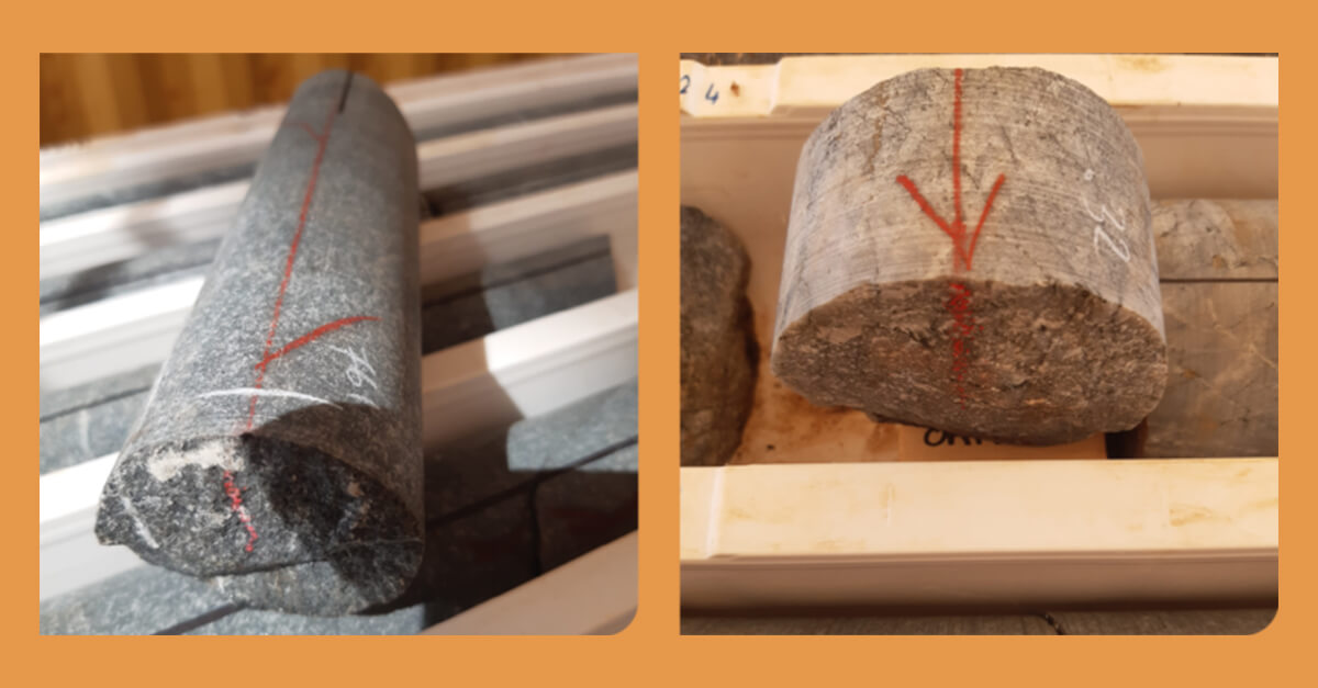
- Intact rock strength testing (Hoek Triaxial, Brazilian Tensile and Consolidated Drained Triaxial
- Rockmass logging – domain logging with the goal of providing Geological Strength Index (GSI) for the identified geotechnical design domains.
- Structural defect data collection by means of the Acoustic Televiewer
- Pre-mining groundwater level and hydraulic conductivities provided by hydrogeological field studies.
- In-situ stress and earthquake loading inferred from nearby operations and the earthquake hazard map of Australia
Initial studies indicated the potential for very steep overall slopes in one area of the pit, which raised queries in terms of its validity. Consequently, further analysis was carried out specifically looking at the potential influence of explicit structure. The goal of the analysis was to verify that there was no ‘geotechnical’ reason why the steeper walls would not be sustainable.
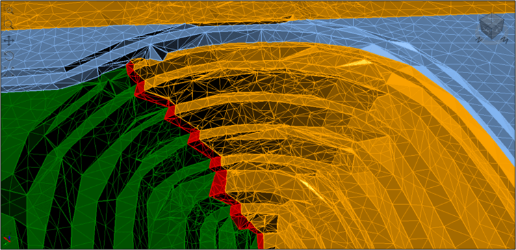
Figure 1 – Steep pit endwall. Factor of safety ~5.3
Inclusion of explicit defects was required, in order that overall slope kinematics and rockmass quality could be included. The measured defect sets and their spacings are known and shown below.
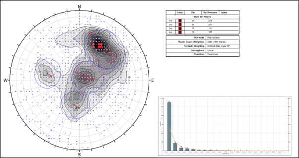
Figure 2 – Structural defects – orientation and spacing distribution (for set 1)
The structural defect statistics were used to define a DFN in RS3, as below. The region of interest was selected to encompass the pit endwall under investigation, and this region was also defined as a ‘plastic region’ for the purposes of focusing the Shear Strength Reduction (SSR) analysis.
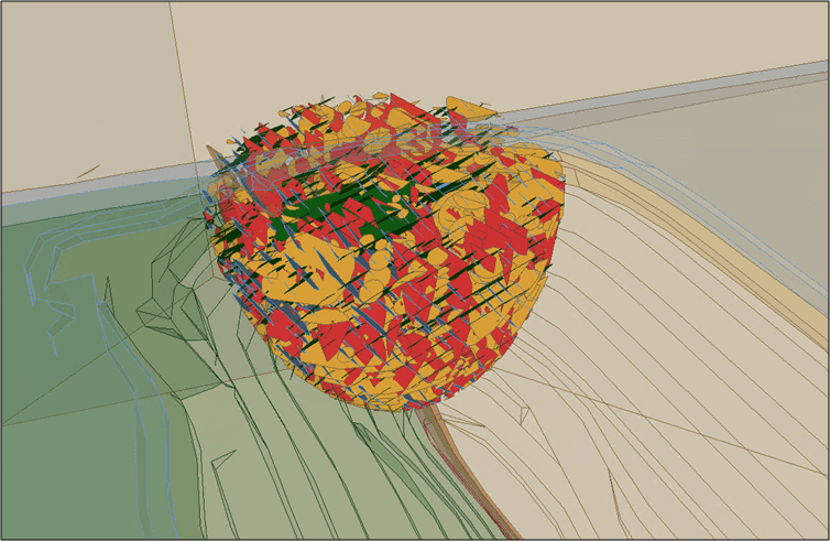
The analysis resulted in a SRF (FoS) of 3.4, which is less than the SRF obtained without the DFN, but still large enough to meet the design acceptance criterion (in this case FoS > 1.5).
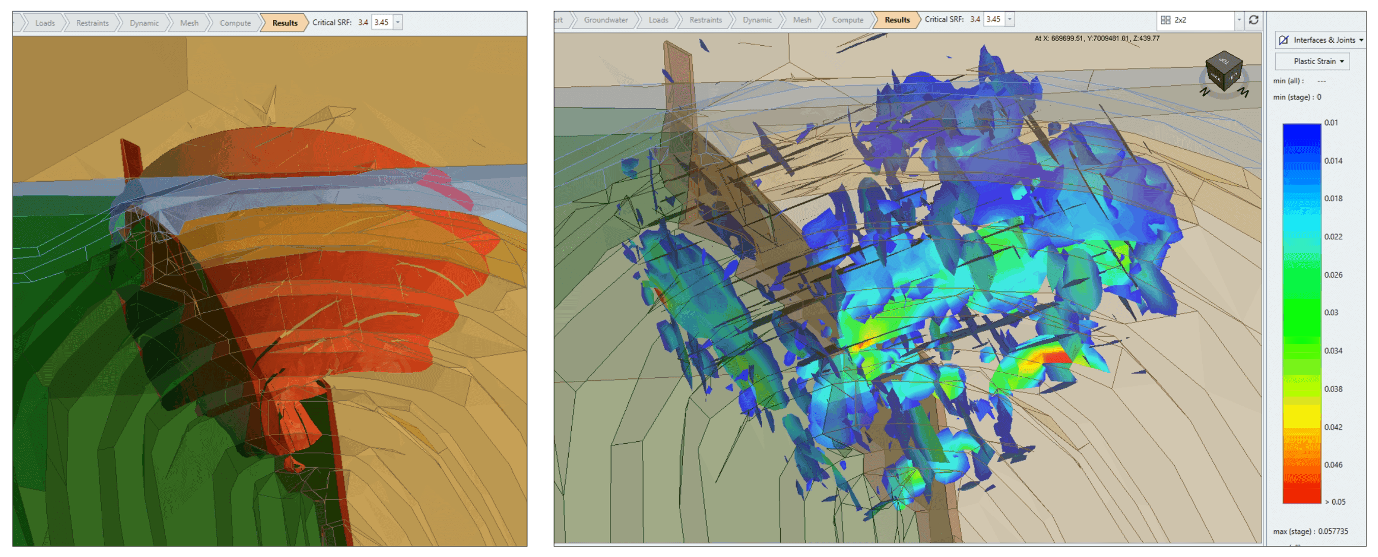
The aim of the analysis was thus achieved by the application of a realistic DFN to ‘downrate’ the rockmass explicitly (rather than by means of GSI, which is a typical approach).
Moving Forward with DFN’s
Modelling Discrete Fracture Networks represents a fundamental shift towards a more holistic and true-to-reality representation of subsurface geological conditions, forever changing the way we approach geotechnical analyses. This example of an open pit mine reinforces this idea and exemplifies a better understanding of how discontinuities impact slope stability analysis can lead to more informed design decisions.
Written by Gordon Sweby, our Principal Consulting Geotechnical Engineer.
View his profile >
The MGT Way is engineering advice
grounded in rigorous data analysis, enabling robust design.
Contact Us >
Our Services >
Meet the Team >
Explore Our Projects >
First published by Rocscience >